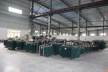


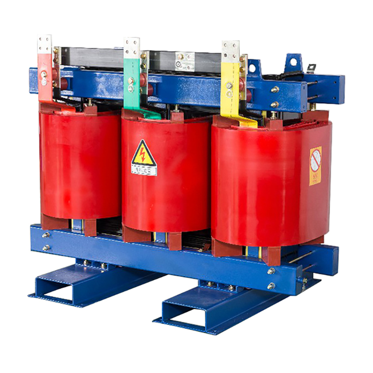
Oil immersed power transformer
One of the important equipment in power supply and distribution system of industrial and mining enterprises and civil buildings
The distribution transformer is one of the important equipment in the power supply and distribution system of industrial and mining enterprises and civil buildings. It reduces the 10 (6) kV or 35 kV network voltage to the 230/400 V bus voltage used by users. This product is applicable to AC 50 (60) Hz, three-phase maximum rated capacity 2500kVA (single-phase maximum rated capacity 833kVA, single-phase transformer is generally not recommended), and can be used indoors (outdoors). When the capacity is 315kVA or less, it can be installed on the pole. The ambient temperature is not higher than 40 ℃, not lower than – 25 ℃, the maximum daily average temperature is 30 ℃, the maximum annual average temperature is 20 ℃, and the relative humidity is not more than 90% (ambient temperature 25 ℃), The altitude shall not exceed 1000m. If it is not in conformity with the above conditions, appropriate quota adjustment shall be made according to the relevant provisions of GB6450-86.
Product Selection Guide
Oil immersed transformer is also called oil immersed test transformer.
Product introduction
1000kVA and above oil immersed transformers must be equipped with outdoor signal thermometers and can be connected to remote signals. Oil immersed transformers of 800kVA and above shall be equipped with gas relay and pressure protection device. Oil immersed transformers of 800kVA and below can also be equipped with gas relay according to the use requirements and through consultation with the manufacturer. Dry type transformers shall be equipped with temperature measuring devices according to the manufacturer’s regulations, generally 630kVA and above transformers.
The products are classified according to the phase number of a single transformer, which can be divided into three-phase transformers and single-phase transformers. In three-phase power systems, three-phase transformers are generally used. When the capacity is too large and limited by transportation conditions, three single-phase transformers can also be used to form a transformer bank in three-phase power systems.
Product Classification
According to the number of windings, it can be divided into two winding transformers and three winding transformers. Generally, transformers are double winding transformers, that is, there are two windings on the iron core, one is the primary winding and the other is the secondary winding. The three winding transformer is a transformer with large capacity (above 5600 KVA), which is used to connect three different voltage transmission lines. In special cases, there are also transformers with more windings.
According to the structure, it can be divided into core type transformer and shell type transformer. If the winding is wrapped around the iron core, it is an iron core transformer; If the iron core is wrapped around the winding, it is a shell type transformer. However, they are slightly different in structure and have no essential difference in principle. All power transformers are iron core type.
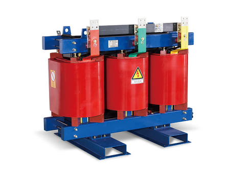
According to insulation and cooling conditions, it can be divided into oil immersed transformer and dry type transformer. In order to strengthen the insulation and cooling conditions, the core and winding of the transformer are immersed together in the oil tank filled with transformer oil. In special cases, such as street lamps and mine lighting, dry-type transformers are also used.
In addition, there are various special transformers for special purposes. For example, high-voltage transformer for test, transformer for electric furnace, transformer for electric welding and transformer for SCR circuit, voltage transformer and current transformer for measuring instrument.
Key points of product selection
Load property 1) When there are a large number of primary or secondary loads, it is advisable to install two or more transformers. When one of the transformers is disconnected, the capacity of the remaining transformers can meet the power consumption of primary and secondary loads. 1、 The secondary load shall be concentrated as much as possible and not too dispersed.
Nature of load
2) When the seasonal load capacity is large, special transformers should be installed. For example, the load of air conditioners and refrigerators in large civil buildings and the electric heating load for heating.
3) When the concentrated load is large, special transformers should be installed. Such as large heating equipment, large X-ray machine, electric arc furnace, etc.
4) When the lighting load is large or the power and lighting use of common transformer seriously affect the lighting quality and bulb life, special transformer for lighting can be set. Generally, power and lighting share the same transformer.
Under normal medium conditions, oil immersed transformers or dry-type transformers can be selected, such as industrial and mining enterprises, agricultural independent or attached substations, residential independent substations, etc. The transformers available are S8, S9, S10, SC (B) 9, SC (B) 10, etc.
Operating environment
Power load 1) The capacity of distribution transformer shall be calculated by integrating the capacity of facilities of various electrical equipment (generally excluding fire load). The apparent capacity after compensation is the basis for selecting the capacity and number of transformers. The load rate of general transformer is about 85%. This method is simple and can be used to estimate the capacity.
Power load
2) In GB/T17468-1998 Guide for Selection of Power Transformers, it is recommended that the capacity of distribution transformers be selected according to GB/T15164-94 Load Guide for Oil immersed Power Transformers or GB/T17211-1998 Load Guide for Dry type Power Transformers and the calculated load. The above two guidelines provide computer programs and normal cycle load diagrams to determine the capacity of distribution transformers.
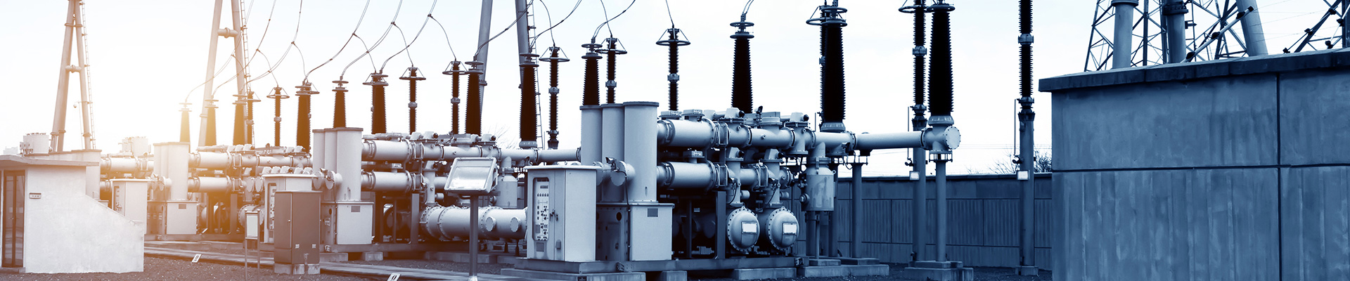
Key points of construction and installation
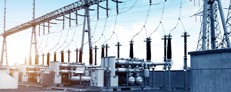
The distribution transformer is an important component of the substation, and the oil immersed transformer is generally installed in a separate transformer room.
Rely on oil as cooling medium, such as oil immersed self cooling, oil immersed air cooling, oil immersed water cooling and forced oil circulation. The main transformer of the general booster station is oil immersed, with a transformation ratio of 20KV/500KV or 20KV/220KV. The general power plant used to drive the auxiliary transformer with its own load (such as coal mill, induced draft fan, forced draft fan, circulating water pump, etc.) is also an oil immersed transformer, with a transformation ratio of 20KV/6KV.
The oil immersed transformer shall be fully oil filled sealed type. Corrugated oil tank shell is a permanently sealed oil tank with its own elasticity to adapt to oil expansion. Oil immersed transformers have been widely used in various power distribution equipment.
Performance characteristics
a. The low voltage winding of oil immersed transformer generally adopts the cylindrical structure of copper foil winding, except that the copper conductor is used for small capacity; High voltage winding adopts multi-layer cylindrical structure to balance the ampere turn distribution of the winding, with small magnetic leakage, high mechanical strength and strong short-circuit resistance.
b. The iron core and winding adopt fastening measures respectively. The fastening parts such as the height of the device and the low-voltage lead are equipped with self-locking locknuts. The structure without hanging core is adopted, which can withstand the shock of transportation.
c. The coil and iron core are vacuum dried, and the transformer oil is vacuum filtered and injected to minimize the moisture inside the transformer.
d. The oil tank adopts corrugated sheet, which has breathing function to compensate the volume change of oil caused by temperature change. Therefore, the product has no oil conservator, obviously reducing the height of the transformer.
e. As corrugated sheets replace oil conservator, transformer oil is isolated from the outside world, which effectively prevents oxygen and water from entering and leading to the decline of insulation performance.
f. According to the above five performance points, it is ensured that the oil immersed transformer does not need to change oil during normal operation, which greatly reduces the maintenance cost of the transformer and extends the service life of the transformer.
fault analysis
1. Oil leakage at welding point
It is mainly due to poor welding quality, faulty welding, desoldering, pinholes, sand holes and other defects in the welds. When the oil immersed transformer leaves the factory, it is covered with welding flux and paint, and hidden dangers will be exposed after operation. In addition, electromagnetic vibration will cause welding vibration cracks, causing leakage. If leakage has occurred, first find out the leakage point, and do not omit it. For the parts with serious leakage, flat shovels or sharp punches and other metal tools can be used to rivet the leakage points. After controlling the leakage amount, the surface to be treated can be cleaned. At present, polymer composite materials are mostly used for curing. After curing, the long-term leakage control can be achieved.
2. Seal leakage
The reason for poor sealing is that the seal between the box edge and the box cover is usually sealed with oil resistant rubber rod or rubber gasket. If the joint is not handled properly, it will cause oil leakage. Some are bound with plastic tape, and some directly press the two ends together. Due to rolling during installation, the interface can not be pressed firmly, which can not play a sealing role, and still leaks oil. FusiBlue can be used for bonding to make the joint form a whole, and oil leakage can be greatly controlled; If the operation is convenient, the metal shell can also be bonded at the same time to achieve the purpose of leakage control.
3. Leakage at flange connection
The flange surface is uneven, the fastening bolts are loose, and the installation process is incorrect, resulting in poor fastening of the bolts and oil leakage. After tightening the loose bolts, seal the flanges, and deal with the bolts that may leak, so as to achieve the goal of complete treatment. Tighten the loose bolts in strict accordance with the operation process.
4. Oil leakage from bolt or pipe thread
When leaving the factory, the processing is rough and the sealing is poor. After the oil immersed transformer is sealed for a period of time, oil leakage occurs. The bolts are sealed with high polymer materials to control leakage. Another method is to screw out the bolt (nut), apply Forsyth Blue release agent on the surface, and then apply materials on the surface for fastening. After curing, the treatment can be achieved.
5. Leakage of cast iron
The main causes of oil leakage are sand holes and cracks in iron castings. For crack leakage, drilling crack stop hole is the best method to eliminate stress and avoid extension. During treatment, lead wire can be driven into the leakage point or riveted with a hammer according to the condition of the crack. Then clean the leakage point with acetone and seal it with materials. Cast sand holes can be directly sealed with materials.
6. Oil leakage from radiator
The radiator tubes are usually made of welded steel tubes by pressing after being flattened. Oil leakage often occurs in the bending and welding parts of the radiator tubes. This is because when pressing the radiator tubes, the outer wall of the tubes is under tension and the inner wall is under pressure, resulting in residual stress. Close the upper and lower flat valves (butterfly valves) of the radiator to isolate the oil in the radiator from the oil in the tank and reduce the pressure and leakage. After determining the leakage position, appropriate surface treatment shall be carried out, and then Faust Blue materials shall be used for sealing treatment.
7. Oil leakage of porcelain bottle and glass oil label
It is usually caused by improper installation or seal failure. Polymer composites can well bond metal, ceramics, glass and other materials, so as to achieve the fundamental control of oil leakage.
Cooling mode
During the operation of oil immersed power transformer, the heat of winding and iron core is transferred to oil first, and then to cooling medium through oil. The cooling methods of oil immersed power transformers can be divided into the following types according to the capacity:
1. Natural oil circulation natural cooling (oil immersed self cooling)
2. Natural oil circulating air cooling (oil immersed air cooling)
3. Forced oil circulating water cooling
4. Forced oil circulating air cooling
Normal service conditions
The altitude does not exceed 1000m indoor or outdoor
Maximum ambient temperature+40 ℃ Maximum daily average temperature+30 ℃
Maximum annual average temperature+20 ℃ Minimum temperature – 25 ℃
Transformers operating under special conditions can be provided according to user requirements.
Executive standards
a. GB1094.1~2-1996, GB1094.3,. 5-2003 Power Transformers;
b. GB/T6451-2008 Technical Parameters and Requirements for Three phase Oil immersed Power Transformers.
fault analysis
Common faults of transformer in operation include faults of winding, bushing, tap changer, iron core, oil tank and other accessories.
1. Winding fault
It mainly includes turn to turn short circuit, winding grounding, phase to phase short circuit, broken wire and open joint welding.
2. Casing failure
The transformer bushing is encrusted, causing pollution flashover in heavy fog or light rain, which causes single-phase grounding or interphase short circuit at the high-voltage side of the transformer.
3. Serious leakage
The oil leakage of the transformer during operation is serious or continuously overflows from the damaged part, so that the oil level gauge can no longer see the oil level. At this time, the transformer should be stopped immediately for leakage repair and refueling. The reasons for the oil leakage of the transformer include weld cracking or seal failure, and the oil tank is severely corroded and damaged due to the impact of external force of vibration during operation.
4. Tap changer failure
Common faults include poor contact or inaccurate position of tap changer, melting and burning of contact surface, discharge of interphase contacts or discharge of each tap.
5. Fault caused by overvoltage
When the transformer in operation is struck by lightning, due to the high potential of lightning, it will cause external over-voltage of the transformer. When some parameters of the power system change, it will cause internal over-voltage of the transformer due to electromagnetic oscillation. The transformer damage caused by these two types of over-voltage is mostly the breakdown of the main insulation of the winding, resulting in transformer failure.
6. Failure of iron core
The failure of the iron core is mostly caused by the insulation damage of the through screw of the iron core column or the clamping screw of the iron core.
7. Oil leakage
The oil level of transformer oil is too low to expose the bushing leads and tap changers to the air, which will greatly reduce the insulation level, so it is easy to cause breakdown discharge.
Fire safety measures
Special attention shall be paid to fire safety measures for oil immersed transformers.
1. The fire separation between oil immersed transformer with oil content of more than 2500kg and oil filled electrical equipment with oil content of 600kg – 2500kg shall not be less than 5m.
2. When the fire separation between two adjacent oil immersed transformers does not meet the requirements, fire partition or fire water curtain shall be set at the top of fire partition. Only fire partition wall or fire water curtain can be set between single-phase oil immersed transformers.
3. When the distance between the outer wall of the power house and the outer edge of the outdoor oil immersed transformer is less than that specified in the specification table, the outer wall shall adopt a firewall. The distance between the wall and the outer edge of the transformer shall not be less than 0.8m.
4. When the outer wall of the power house is within 5m from the outer edge of the oil immersed transformer, no doors, windows and holes shall be opened below the horizontal line of the total thickness of the transformer plus 3m and within the range of the outer edges on both sides plus 3m; The fire endurance of the doors and fixed windows on the firewall outside its scope shall not be less than 0.9h.
5. When the oil volume of an oil immersed transformer and other oil filled electrical equipment is more than 1000Kg, an oil storage pit and a public oil sump shall be set, and the transformer pebbles shall be placed for fire prevention and oil unloading.
6. The oil immersed transformer shall be equipped with fixed water spray and other fire extinguishing systems according to the current relevant specifications. The oil immersed service transformer shall be set in a separate room. The door of the room shall be a Class B fire door that opens outwards and leads directly to the outside of the room or corridor. It shall not open to other rooms.
Oil system
The oil immersed transformer has several independent oil systems isolated from each other. During the operation of oil immersed transformers, the oil in these independent oil systems is not connected with each other, and the oil quality is different from the operating conditions. Gas chromatography analysis of oil shall be conducted separately to determine whether there is a potential fault.
(1) Oil system in the main body. The oil system connected with the oil around the winding is the system inside the main body, including the oil in the cooler or radiator, the oil in the oil conservator, and the oil in the oil filled bushing at 35kV and below.
During oil filling, the gas vent plug stored in the oil system must be drained. Generally speaking, the above components shall have their own vent plugs. The oil in the main body mainly serves as insulation and cooling. Oil can also increase the electrical strength of insulating paper or cardboard. During vacuum oil injection, if some parts cannot bear the same vacuum strength as the main oil tank, temporary gate shall be used for isolation, such as the gate valve between the oil conservator and the main oil tank. The head of the submersible pump on the cooler shall be enough to avoid air suction due to negative pressure. The oil system shall be equipped with a protection system of pressure relief device to eliminate the pressure generated when the device body has faults.
(2) Oil in the on load tap changer change-over switch room. This part of oil has its own protection system, namely flow relay, oil conservator and pressure relief valve. The oil in this switch room insulates and extinguishes the current. The oil will flow into the oil generated when the load current is cut off by the switch. The oil system shall have good sealing performance, and the sealing performance shall be protected even if the arc pressure is generated during switching.
Although the oil in the transfer switch room of the on load tap changer is isolated from the oil in the main body, during vacuum oil injection, in order to avoid damaging the seal of the transfer switch room, vacuum oil injection should be carried out simultaneously with the oil in the main body. During vacuum oil injection, the two systems should have the same vacuum degree. If necessary, the oil conservator of this system should also be isolated during vacuum pumping. For structural convenience, the oil conservator of the main body and the oil conservator of the switch room are designed as a mutually isolated whole.
(3) Fully sealed with voltage level of 60kV and above. This oil system is mainly used for insulation, or to increase the electrical strength of the insulating paper in the oil capacitive bushing. When oil is injected into the main body, the terminal block at the end of the sleeve shall be sealed to avoid air intake.
(4) Oil in high-voltage outlet box, or oil in point gas outlet box. The high-voltage outgoing line of three-phase 500kV transformer is isolated by the corrugated insulation oil system. This oil system is mainly used for insulation.
In order to simplify the structure, the oil system can also be connected with the oil system in the main body through connecting pipes or designed as a separate oil system.
(5) When conducting various insulation tests on oil immersed transformers, the first step is to release the gas that may be stored through the vent plug. The potential failure can be predicted by analyzing the gas in oil chromatographic analysis of each system. Each oil system shall meet the operation requirements, such as the change of oil volume during the expansion and contraction of absorption oil, valves for oil drainage, vent plugs, isolation valves between cooler and radiator and main oil tank, etc. Each oil system has a good sealing performance. The oil in the on load tap changer change-over switch room can be replaced independently without draining the oil in the main body. During transportation, the oil in the main body can be drained and filled with dry nitrogen.
Installation and commissioning
Before the installation of transformer 1. Man hour quota: (according to the national quota standard) the comprehensive man days required for body installation are 21 man days. The work includes: unpacking inspection, body in place, body inspection, cleaning of casing, conservator and radiator, oil column test, installation of accessories, fabrication and installation of sizing block and wheel stopper, additional column and overall seal test after installation, grounding, paint repair, etc. Whether the transformer needs to be dried during installation shall be determined after inspection and judgment. The required working days are 20 days when the iron loss drying method is used, and 3.38 working days/ton for oil filtration. The man days required for commissioning shall be calculated separately.
Before transformer installation
2. Layout of installation site: overhaul and assembly of power transformer should be carried out in the maintenance room. If there is no maintenance room, it is necessary to choose a temporary installation site, preferably near the foundation platform of the transformer, so that the transformer can be in place, or installed locally on the foundation platform. There should be tents on the outdoor site. The temporary installation site must be convenient for transportation, with flat roads and sufficient width. The ground should be solid, flat and dry, away from smoke windows and water towers, and the distance from nearby buildings should meet the fire protection requirements.
3. Designated safety measures: ① Prevent personal electric shock, fall and other accidents. ② Prevent the insulation from overheating. ③ Prevent fire. ④ Prevent something from falling into the fuel tank. ⑤ Prevent accessories from being damaged. ⑥ Prevent the transformer from overturning.
4. Formulate technical measures: ① Prevent the transformer core from getting damp. ② How to ensure good contact of all connecting parts. ③ All parts shall be well sealed without oil leakage. ④ How to ensure transformer insulation and oil insulation.
5. Basic procedures for installation: ① preparation (tools, materials, equipment, drawings) ② inspection and judgment of insulation (mainly coil and iron core) ③ inspection of accessories (complete and intact) ④ core lifting inspection (to prevent moisture absorption and tools, parts, etc. from falling into the oil tank) ⑤ accessory installation (visual inspection, insulation measurement and tight test) ⑥ final work. ⑦ Hand over test. ⑧ Commissioning.
6. Organization and division of labor of staff: ① installation commander in chief and technical director ② safety officer ③ oil filter group ④ lifting and transportation personnel ⑤ testing personnel ⑥ installation personnel.
7. Requirements for transformer room: ① Class I fire protection ② Good ventilation ③ Sufficient safety distance ④ Foundation platform shall be firm ⑤ Lifting facilities shall be in good condition.
8. Preparation of tools and materials:
⑴ Install machines and tools (such as vacuum pump, oil pump, oil tank, compressed air machine, oil filter, electric welding machine, portable lamp transformer, valves, various wrenches, etc.)
(2) Test instruments (such as megger, dielectric loss angle tester, step-up transformer, voltage regulator, ammeter, voltmeter, power meter, thermometer, etc.)
(3) Lifting machines and tools (such as cranes, hangers, lifting beams, hoists, wire ropes, pulleys, chain cranes, etc.)
(4) Insulating materials (such as insulating oil, cardboard, cloth tape, electric board insulating paint, etc.)
(5) Sealing materials (such as right resistant rubber gasket, asbestos rope, steel base, shellac paint, nylon rope, etc.)
(6) Bonding materials (such as epoxy resin adhesive, glue, cement, mortar, etc.)
(7) Cleaning materials (such as white cloth, alcohol, gasoline, etc.)
(8) Other materials (such as asbestos board, square wood, electric wire, steel pipe, oil filter paper, Vaseline oil, enamel paint, etc.)
9. External inspection of transformer:
① No mechanical damage
② The box cover bolts are intact
③ The gasket is well sealed
④ No defects on casing surface
⑤ No oil leakage
⑥ No rust, complete paint
⑦ All accessories are intact
⑧ The wheel gauge of the roller is consistent with the gauge of the foundation rail.
Requirements for core lifting inspection 1. The transformer will be subject to large vibration after long distance transportation, so it is necessary to conduct body inspection. The inspection of transformer body is divided into hanging core and hanging cover. Whether the hanging core or the hanging cover, the inspection contents are consistent. The core lifting inspection shall be completed within one working day to speed up the inspection process.
Requirements for core lifting inspection
2. Take the core suspension inspection as an example: ⑴ The core suspension of the transformer shall be carried out indoors. If there is a tent outdoors, the core suspension is prohibited in case of rain, snow, fog, wind and sand and other bad weather. (2) The temperature of suspended core shall not be lower than zero in winter, or the transformer shall be heated to make the core temperature 10 ℃ higher than the ambient temperature (3) The shorter the time the core is exposed to the air, the better. The relative humidity shall not exceed 16 hours when it is 65%, and 12 hours when it is 25%. The calculation time starts from oil drainage to oil injection. (4) When the relative humidity in the weather exceeds 75%, core lifting inspection is not allowed. (5) During core lifting inspection, special attention shall be paid to prevent parts and tools from falling into the oil tank.
Preparation before core lifting ⑴ Preparation of tools and materials: such as oil storage tank, oil filter, complete set of wrench, Dao Ben, oil resistant rubber rope, white cloth, insulating cardboard, etc. (2) Preparation of lifting equipment: such as crane, chain block, chain block, tripod, wire rope, etc. If chain block is used, the hanger must be erected according to the height and weight of the transformer. (3) Transformer oil treatment, oil sample analysis and test, and oil filtering preparation, including oil filter paper. (4) Prepare the oil pan and set out the core by hand.
Preparation before core lifting
The height (h) of the hanger shall not hinder the lifting out of the body. Therefore: h=h1+h2+h3+h4+h5 where=h1 height of oil tank h2 height of machine body h3 height of sling sleeve h4 minimum distance of pulley (or chain block) h5 standby height (300~500mm) 1. lifting beam 2. pulley 3. rope sleeve 4. machine body 5. oil tank
Core lifting steps (1) Select the core lifting position and drain the oil (below the large plate)
Core lifting steps
(2) Remove the explosion-proof cylinder, conservator and gas relay
(3) Remove the bolts of the large cover
(4) Use the balance iron to lift the iron core out and put it in the oil pan
(5) Inspection:
① Core insulation
② Core insulation
③ Insulation of threaded bolt
④ Tap changer contact insulation
⑤ High and low voltage lead
⑥ Fuel tank sundries
⑦ Whether the radiator pipe is blocked
⑧ Telemetering insulation resistance
⑨ Measuring DC resistance
(6) If no problem is found after inspection of all items, reinstall the iron core in the oil tank in time
(7) Tighten the bolts of the large cover
(8) Installation of removed accessories
(9) Inject qualified oil
(10) Perform a full set of withstand voltage test (11) after 6-10 hours of static state.
Installation requirements 1. The transformer foundation track shall be horizontal, and the conservator side shall have a 1-1.5% slope.
Installation requirements
2. The transformer shall be reinforced
3. The bushing shall not be stressed by the primary and secondary leads of the transformer.
4. The transformer shell is firmly connected with the neutral point and grounding device to form a trinity 5.800KVA (gas relay is installed)
Trial operation 1. The transformer can only be commissioned after all test items are qualified.
test run
2. A comprehensive inspection shall be carried out for the transformer before trial operation.
3. The transformer shall undergo 5 times of impact test (closing test).
4. The no-load operation time is related to the transformer capacity, which is generally not less than 24 hours.
5. After the no-load operation time is completed, the transformer shall be loaded again.
Oil treatment 1. Pressure filtration method: the insulating oil used for power transformers must have insulating and thermal conductivity properties (national standard). At the installation site, pressure filtration method is commonly used to complete the general drying (removal of moisture) and purification (removal of dirt) of insulating oil.
Oil treatment
2. Open valves 8 and 11, then start the oil pump, and then open valves 6 and 7. When stopping the oil, first close 6 and 7, then stop the oil pump, and then close the valves of 8 and 11. (2) During normal operation, the pressure gauge works normally under the pressure of 3 * 10~4 * 10Pa. If impurities and oil paper are blocked, the pressure increases. When the pressure reaches 6 * 10Pa, it must stop and replace the filter paper. ⑶ The filter paper shall be dried in an 80-90 ℃ oven for 24 hours before use and placed in a clean container. (4) The filter screen shall be cleaned every 10-15 hours. At the beginning, the oil shall be filtered for 3-5 minutes. The oil outlet shall be sent back to the sump oil tank through valve 10 for re filtering. The oil accumulated in the oil filter shall be sent back to the sump oil system through valve 9 for re filtering. The above filtering oil shall be subjected to essence and drying for many times until it is qualified.
3. Live oil filtering of transformer: ⑴ When the voltage is higher than 10V, live oil filtering should not be used. Because more bubbles are generated during filtering, bubbles will dissociate under the action of higher voltage, which will deteriorate the insulation performance of the oil and lead to internal discharge. During live oil filtering, the gas released from the oil in the gas relay shall be discharged regularly. (2) When electrified oil filtering, the oil pipe and oil filter shall be reliably grounded to protect the personal safety of the staff. The staff shall be professional, supervised and wear insulation articles. (3) Operation: at the interface of diagonal valves 4 and 5, connect the pressure type oil filter buckle, extract oil from valve 4, return to the oil tank from valve 5, and filter it through multiple cycles until it meets the standard.
Transformer test 1. Telemetry of insulation resistance: ⑴ Telemetry items, high voltage to low voltage and ground (shell), low voltage to high voltage and ground (shell), ⑵ 2500 V tramegger shall be selected for appearance inspection. The tramegger shall be in good condition, with complete external customers, flexible handle, no long resistance of pointer and no damage of glass. (3) Conduct an open circuit test on the megger, separate two probes, shake the handle of the megger up to 120y/min, and point the pointer to infinity (∞). Short circuit test: shake the handle of the megger, and connect the two probes instantaneously, and point the pointer to “0″ (zero), indicating that the megger is normal. (4) Acceptable value: at the temperature of 20 ℃, the new transformer shall not be less than 450M Ω, and it shall not be less than 300M Ω during operation. This value shall not be 30% lower than the last value. ⑸ The absorption ratio R60/R12 should be 1.3 times at 10-30 ℃.
Test of transformer
2. DC resistance measurement: it can measure the welding quality of the wires and leads inside the transformer, whether the parallel branches are connected correctly, whether there is interlayer short circuit or internal broken wire, whether the tap changer, bushing and leads are in good contact, etc.
3. Measuring method: with bridge, it can be measured by bridge, and it can be directly read with high accuracy. Without bridge, it can be measured by voltage drop method. The wiring of DC resistance can be measured by voltage drop method. a) Measure small resistance. b) Measure large resistance. 1 – Measured coil. 2 – Knife switch. 3 – Battery. 4 – Voltmeter. 5 – Ammeter. DC resistance calculation formula: where: U – Voltmeter reading (mv) I – Ammeter reading (A) Transformer with tap changer. During handover or overhaul, Measurements shall be made at all tap locations. When the three-phase transformer has a neutral point outgoing line, the resistance of each phase line diagram shall be measured. When there is no neutral point outgoing line, the line resistance can be measured.
During measurement, all non tested wiring diagrams shall be open circuit and not short circuited. During the measurement, it is necessary to wait for the current to stabilize before reading, and pay attention to personal safety.
4. Judgment standard: the difference between the DC resistances of each phase line diagram shall not be greater than 2% of the average value of the three items, and the relative change compared with the previous measurement shall not be greater than 2%. In order to compare with the factory measured value or the past measured value, the DC resistance value shall be converted to the value at the same temperature. The formula is as follows: copper wire: aluminum wire: where: Re – Θ DC resistance value measured at ℃. Rt – DC resistance value converted to t ℃. Cause of fault: ⑴ Poor contact of tap changer ⑵ Poor welding and fracture of coil or lead. (3) The connection between the bushing conductive rod and the lead is poor (4) The coil is short circuited between turns or layers.
5. Group test:
⑴ Polarity measurement of single-phase transformer. The purpose of three-phase transformer measurement group is to make correct connection and judge whether the transformer can operate in parallel.
(2) Polarity measurement: DC measurement can be used as well as AC measurement. DC measurement is also introduced: 2-4V batteries and DC voltmeters with zero in the center are selected for DC test wiring. When closing the switch, the meter needle swings in the positive direction, while when opening the switch, the meter needle swings in the negative direction, reducing the polarity. On the contrary, add polarity.
(3) Three phase transformer wiring group measurement includes DC method and AC method.
Other information
Even in the same oil system, oils with different oil bases cannot be mixed.
Each oil system shall pay attention to the oil characteristics at negative temperature, such as high viscosity, poor fluidity and poor heat dissipation of the oil in the main body at negative temperature. The negative temperature of the oil in the transfer switch room of the on load tap changer will affect the lengthening of the switching process and increase the temperature rise of the transition resistance.
For the oil system in the main body of the EHV oil immersed transformer, attention should also be paid to the phenomenon of oil flow electrification, and the transition from oil flow electrification to oil flow discharge should be prevented. It is necessary to control the resistivity of the oil, the speed of each part of the oil, and the space for releasing the electric charge in the oil.
Post time: Oct-22-2022